
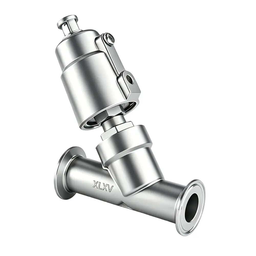
Clamped Pneumatic Angle Seat Valve – A

  • Nominal Size (DN): DN8–DN100 (1/4″–4″)
  • Pressure Rating: 0–16 bar (0–232 psi), with vacuum service down to -0.9 bar available as an option
  • End Connections: Threaded, welded, tri-clamp, flanged; customizable upon request
  • Standards: ISO, DIN, 3A
  • Body Materials: CF8, CF8M, SS316L, Duplex 2205, Duplex 2507, 904L, 310S, Titanium Grade 2 (TA2), etc.
  • Actuator Material: Stainless Steel 304
  • Applicable Media: Water, neutral gases or liquids, alcohol, oil, fuel, steam, organic solvents, acidic and alkaline solutions, etc.
  • Media Temperature Range: -10°C to 220°C

Product details

As a high-precision fluid control component commonly used in industrial automation, the pneumatic quick-install angle seat valve offers advantages such as rapid on-off response, suitability for high-frequency cycling, stable operation, and high hygienic standards. It is widely applied in clean and automated process scenarios across the food, pharmaceutical, chemical, and water treatment industries.

Pneumatic Quick-Install Angle Seat Valve – Product Features

1. Optimized Flow Path for High Flow Capacity:The Y-angle seat flow path design ensures smooth passage and low flow resistance. Compared with conventional globe valves of the same bore size, flow capacity is increased by approximately 30%, with lower pressure drop. It is ideal for high-flow conveying applications while maintaining a compact installation footprint.

2. Quick-Install Configuration for Easy Maintenance:Supports multiple connection types, including sanitary tri-clamp, threaded, and flanged ends. The clamp-type quick-install design requires no welding, enabling rapid assembly and disassembly, convenient cleaning, and eliminates dead zones, fully meeting the requirements of hygienic process applications.

3. Fast Pneumatic Response and Flexible Control:Equipped with either single-acting spring-return or double-acting pneumatic actuators, and compatible with solenoid valves for ultra-fast opening and closing with precise and responsive action. Available in normally closed and normally open configurations, allowing fail-safe status to be set according to process requirements, and adaptable to various automation control logics.

4. Reliable Sealing and Long Service Life:Sealing materials include PTFE and reinforced polypropylene, offering excellent corrosion resistance and suitability for extreme temperatures, with a standard operating range of –30 °C to 180 °C, and high-temperature versions available up to 260 °C and above. The self-lubricating stem seal design reduces friction, prevents contaminant ingress, and withstands millions of high-frequency actuation cycles for durable and stable performance.

5. Visual Indication and Expandable Functionality:An integrated top-mounted mechanical position indicator provides real-time visual status display. Optional limit switches enable remote signal feedback, and manual override is available upon request. The pneumatic actuator head can be rotated 360° to accommodate complex on-site installation layouts.

6. Water Hammer Protection for System Safety:The bottom-in, top-out flow configuration effectively mitigates water hammer effects, reducing fatigue stress on pipelines and valve bodies, thereby enhancing overall system stability and operational safety.

7. Hygienic-Grade Stainless Steel for Broad Applicability:Valve bodies are manufactured from 304, 316, and 316L stainless steel, conforming to ISO, DIN, and 3A sanitary standards. With excellent corrosion resistance and high-temperature tolerance, the valve is suitable for media including water, steam, oils, organic solvents, weak acids and alkalis, as well as food-grade substances. It is extensively used in the pharmaceutical, food and beverage, chemical, and water treatment industries.

Product Specifications

Standardized Installation Instructions


1. Pre-Installation Preparation

Pipeline Cleaning:
Before installation, the pipeline must be thoroughly purged and cleaned to completely remove welding slag, rust, debris, and other solid particles. This is to prevent contaminants from damaging the valve seat sealing surface or causing the valve core to jam. It is recommended to install a filter with a filtration accuracy ≥ 5 μm upstream of the valve to provide long-term protection for internal components.
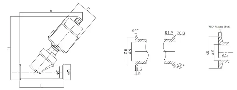
SizeActuator
mm
EHA
DN101.575″1.969″4.528″5.118″
1.969″2.362″5.551″5.906″
DN151.575″1.969″4.528″5.118″
1.969″2.362″5.551″5.906″
DN201.969″2.362″5.709″6.339″
DN251.969″2.362″5.709″6.693″
2.48″2.953″6.575″7.441″
DN322.48″2.953″7.126″8.071″
3.543″4.173″8.74″9.685″
DN402.48″2.953″7.126″8.228″
3.543″4.173″8.78″9.803″
DN502.48″2.953″7.402″8.583″
3.543″4.173″9.016″10.157″
DN653.543″4.173″10.984″11.811″

Valve Inspection:
Verify that the valve model, nominal size, pressure rating, and temperature range are fully compatible with the actual working conditions. Ensure that the valve body, actuator, position indicator, and sealing components are intact, with no damage, deformation, or aging.

System Depressurization:
For retrofit or maintenance on existing pipelines, the process medium supply and control air supply must be shut off in advance. Residual pressure and trapped media must be fully released. Installation may only proceed after confirming the pipeline is completely depressurized and empty to ensure safe operation.


2. Installation Direction & Flow Requirements

Flow Direction Compliance:
A flow direction arrow is cast on the valve body. Installation must strictly follow the indicated direction. Reverse installation is strictly prohibited, as it may cause sealing failure, internal leakage, or abnormal valve operation.

Media-Based Flow Selection:

  • For liquid media, a bottom-inlet / top-outlet flow configuration is recommended to utilize media pressure for assisted sealing, reduce water hammer effects, and extend service life.
  • For gas or steam media, a top-inlet / bottom-outlet configuration may be used to improve shut-off sealing performance. Regular inspection of stem sealing wear is recommended.

Actuator Orientation:
The optimal installation position is with the actuator installed vertically upward, which helps prevent condensate accumulation inside the cylinder and avoids actuator sticking or malfunction.
Where space is limited, horizontal or inclined installation is acceptable; however, proper drainage must be ensured to avoid water accumulation.


3. Piping Connection Requirements

Tri-Clamp (Quick-Install) Connection:
Align the valve and pipeline ferrules, place the sealing gasket centrally, and evenly tighten the clamp. Ensure precise alignment at both ends. Forced misalignment, twisting, or uneven compression is strictly prohibited to avoid sealing failure or leakage.

Threaded / Flanged Connections:
Tighten bolts evenly in stages to prevent unilateral stress, which may cause valve body deformation or sealing failure.

Welded Connections:
Before welding, the pneumatic actuator must be completely removed to prevent high temperatures from damaging sealing elements and internal precision components. After welding, allow the valve body to cool to ambient temperature before reinstalling and commissioning the actuator.


4. Pneumatic System Requirements

The system must use clean, dry, and oil-free compressed air as the power source. The standard operating pressure is 0.4–0.8 MPa, subject to the product nameplate specifications.

It is recommended to install a FRL unit (Filter, Regulator, Lubricator) at the air inlet to ensure air purification and stable pressure supply, guaranteeing smooth actuator operation.

All pneumatic fittings must be securely connected to prevent air leakage or pressure loss, which may cause slow response or incomplete valve actuation.


5. Installation Commissioning & Routine Maintenance

Commissioning:
After installation, connect the air supply and solenoid valve power supply. Perform multiple no-load open/close cycles to verify smooth operation. Check for sticking, abnormal movement, and ensure there is no leakage at valve connections or air fittings. Proper operation confirms successful installation.

Routine Maintenance:

  • Inspect stem packing seals every 6 months and replace if worn.
  • Regularly clean the actuator piston chamber to maintain dryness and cleanliness.
  • For viscous or scaling media, periodically disassemble and clean the valve core and seat to prevent buildup that may affect sealing performance and actuation accuracy.

Common Troubleshooting:

  • If the valve does not operate, first check air supply pressure, solenoid valve coil, and electrical wiring.
  • If leakage occurs in the closed position, inspect whether sealing components are aged or damaged, and whether the valve core or seat is obstructed by debris.